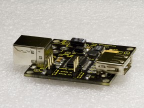
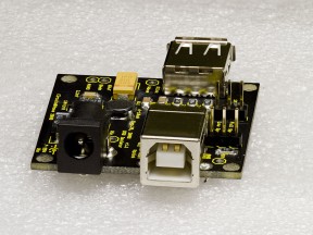
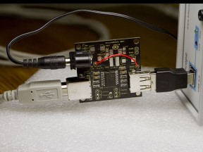
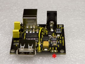
This is assembly guide for Analog Devices ADuM4160-based full/low speed USB Isolator kits from Circuits At Home.
1. Introduction
USB Isolator kits, released in October 2009, has been popular among PC-based test instrument users, software-defined radio operators, and DIY audio builders, to name a few. It is reliable and quite affordable way to provide galvanic isolation between host PC and USB peripheral. In this manual, I give step-by-step instruction on building USB isolator kit and also talk about tweaking and modifying the circuit for certain applications.
Both “Isolator Only” and “Full” Kits are covered.
Before starting assembly, please download the schematic. Eagle CAD files may also be helpful. Finally, this is the store link.
2. Component Identification
|
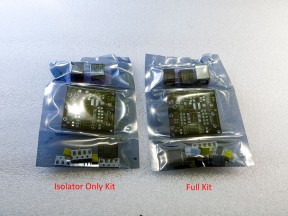
When parts kit arrives in the mail, it usually looks like one on Photo 1 (click on it to make it bigger). Parts are in the lower compartment, PCB – in the middle of the bag, and connectors are on the top. “Full Kit” on the right contains more parts, as well as one extra connector.
No matter which kit you are building, dealing with small unmarked parts is inevitable. These parts are also lightweight so sneezing into a pile of parts is not recommended. Some parts are mounted on a tape – it is generally good idea to keep them this way until the moment you are ready to solder them. The easiest way to get parts out of the bag is to cut the bag along the long edge with scissors. Connectors can stay in the bag for now. For next several steps, a pair of tweezers and magnifier glass will be helpful. |
||
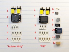
Photo 2 shows small parts of the kit. Again, “Isolator Only” set is on the left aligned in a single column. Two columns on the right is “Full” set. Here is the list:
The rest of the parts are present only in “Full” kit. Most of them have distinctive shape and therefore easily identifiable, but beware of number 6!
|
||
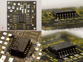
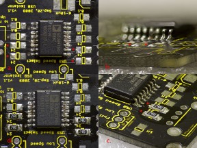
| Step 1. The first piece to solder is ADuM4160. Photo 3a shows correct placement – a notch on the case is facing power supply side of PCB. Photo 3b shows pins aligned to pads and a corner pin soldered. If after making this joint pins become misaligned, heat the solder joint, melt the solder and re-align the part. When everything is good, turn PCB around, check alignment, solder another corner pin, and check alignment again – if misaligned, heat up the joint and re-align. When alignment is good, continue soldering remaining pins on this side (Photo 3c), then turn PCB around and finish other side. When all pins are soldered, run dental pick or X-Acto knife between pins to check for bridges and then inspect your work under magnifier. Photo 3d shows final result. A couple of pins on this picture hold a little bit too much solder, however, there is no bridges so they can be left alone. | |
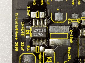
| Step 2 (“Full” kit only). If you are buiding “Full” kit, it’s now time to mount LT1376 IC. “Isolator only” builders please skip to step 3. The soldering technique is similar to Step 1 – align, solder a corner pin, check alignment, solder second corner pin, check alignment again, solder remaining pins, and finally inspect for bridges with dental pick and magnifier glass. Photo 4 shows LT1376 mounted on the board in proper orientation. This IC doesn’t have a notch; instead, it has a small taper on lower (on the photo) edge of the package. Don’t use package markings for reference – they can be printed upside down. | |
|
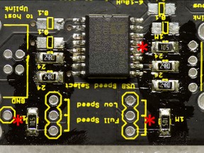
Step 3. In this step, I will be soldering 24 Ohm resistors. Four of them need to be placed on both sides of ADuM4160 IC. Photo 5a shows where they need to go – I placed little red asterisks to the left of each place to make it easier to find on the photo. Before making the shots, I cleaned up flux residue from the PCB with 99% IPA AKA rubbing alcohol using old toothbrush. It’s not really necessary during assembly, unless generous application of flux makes it difficult to recognize part positions. You may also notice that I wiped off extra solder from ADuM4160 pins with solder wick.
Soldering 1206 resistors is much easier than SO packages ( ADuM4160 and LT1376 ). The part has only 2 pads to solder and at the same time big enough to handle with a pair of decent tweezers. All that is necessary is apply flux to the pads, then add small amount of solder to one pad, apply more flux, place the part, melt the solder while holding part in place, check alignment and then solder other pad. The key to success here is correct amount of solder – this amount shall be small. Also, first pad is somewhat harder to do than second, therefore when deciding which one to start with, pick one which has more empty space around – as you can see on Photo 5a, I picked pads facing away from ADuM4160. Photo 5b shows closeup of two pads with correct amount of solder applied. Photo 5c shows a pair of resistors with one side soldered. Don’t forget second pair on the other side of ADuM4160 and then solder other sides of all 4 resistors. Don’t forget to apply flux from time to time. Photo 5d shows final result. |
|
| Step 4. Next I will be placing 1M 1206 resistors. Using technique described in previous step, place 2 resistors next to speed selector jumpers and one next to ADuM4160, as depicted in Photo 6. | |
|
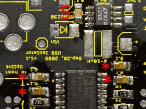
Step 5. Four 0.1uF 1206 capacitors are placed on both sides of ADuM4160. If you are buiding “Full” kit, fifth cap goes next to LT1376. On Photo 7, 4 caps around ADuM4160 are marked with asterisks, and the fifth one is marked with number “5”.
After finishing this step, builders of “Isolator Only” kit may skip to Step 15, where connector placement is shown. |
|
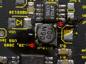
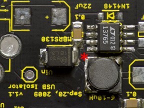
| Step 6 (“Full” kit only). Sumida CDRH5D18 inductor goes next. This part has a lot of thermal capacity so if you can, bump your soldering iron temperature a little. First of all, flip the part around and take a look at the pads. Even though inductor is non-polar, there is a way to solder it incorrectly by placing inductors’ pads across PCB pads. Don’t make this mistake – if you do, de-soldering would be a pain. Second, it is very hard to attach the whole pad to the PCB with soldering iron – the part is basically piece of iron and have large thermal capacity; in addition, pads tend to separate from the case if you overheat it. The easiest way to mount this inductor is to solder two opposite corners, where inductor wire is attached to the pad. Two asterisks on Photo 8 are marking soldering points. | |
| Step 7 (“Full” kit only). MBRS130 Shottky diode is polar – it has a stripe on its package indicating negative terminal. Photo 9 shows correct orientation with asterisk placed next to negative terminal. You may also note a solder bridge from this terminal to adjacent capacitor – this is normal. If you get one while soldering this part – don’t worry, there is actual trace below it. | |
| Step 8 (“Full” kit only). 1N4148 diode is also polar – see Photo 10 for correct placement. | |
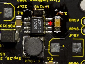
| Step 9 (“Full” kit only). 3300pF capacitor, non-polar, accessible from either end (see Photo 11). You won’t have any trouble soldering it. | |
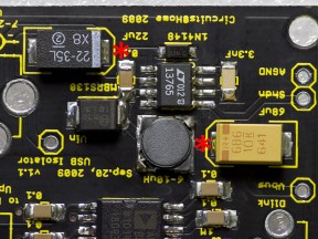
| Step 10 (“Full” kit only). Last step on this side of the board – placing input and output capacitors. Tantalum caps are polar and have familiar stripe on their packages; however, unlike doides, the stripe marks positive terminal. Photo 12 shows correct placement with asterisks placed close to positive terminals. | |
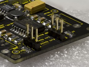
| Step 11 (both kits). In previous step we mounted last SMD piece. We now need to solder several thru-hole parts. Photo 13 shows speed selector jumpers placement. | |
| Step 12 (both kits). Two USB connectors go next. This completed the build for “Isolator Only” builders. To complete “Full” build, one last step is necessary. | |
| Last step(“Full kit” only). Barrel power connector. This concludes the build. |
4. Testing
|
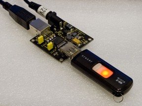
After board is built, it’s good idea to wash it in 99% IPA and check for power-to-ground shorts. Don’t forget to install speed selector jumpers – they have to be set to the same speed on both sides of the isolator. Unless you need to isolate low-speed device, such as keyboard or mouse, set them to Full speed. If you have built Full kit, you need to find suitable wall wart. The power supply accepts wide range of input voltages; it is important to have positive supply on center contact of power supply’s barrel connector. A PC and some USB device are also necessary to test the isolator, USB cable or two may come in handy as well. I usually use USB flash disk with large archive on it. When disk gets detected by OS, I run “Archive check”, generating a lot of traffic while archiving program performs the integrity check of data passing through the isolator.
Picture on the left shows my test setup. For best results, connect them in the following order: power first, then host, then peripheral. If your peripheral is not detected or PC gives detection errors, reconnect it while leaving power and host connected. “Isolator Only” kit has much more powering options. Please refer to “Tweaking” section for some ideas. Testing procedure is similar. What to do if circuit doesn’t work? Checking everything with an ohmmeter is a good idea. Also, very common detection error issue, as well as ways to remedy it, are described in this article. |
5. Isolating
USB isolator breaks galvanic connection between USB host and peripheral. Among other things, this means whatever power and ground noise that exists on one side won’t affect the other. In many cases, the source of noise is PC power supply, however I heard about noisy peripherals too. One of my customers has stage lights controller connected to his laptop adding interference to music playing from laptop’s audio port – the issue was remedied with USB isolator.
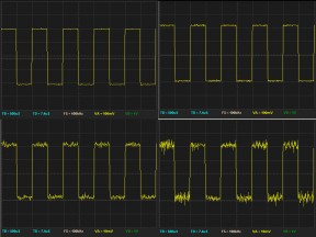
In many cases, isolating peripheral from PC ground reduces noise to undetectable levels. However, for very sensitive equipment, such as USB oscilloscopes, extra steps must me taken to ensure signal integrity. Photo on the left shows 1KHz analog calibrator waveforms displayed on Bitscope 310 USB DSO. Signal amplitude from top to bottom changes from 4V to 400mV to 40mV to 4mV p-p. Left column shows waveform with USB port of the instrument isolated, right column waveforms were obtained with instrument directly connected to the same USB port of the same PC. The results can be easily interpreted – while 4V signal looks pretty much the same on both pictures, smaller signals show more and more noise and 4mV signal on directly connected Bitscope is hard to interpret, let alone measure.
Photo on the right shows the arrangement. In order to reduce interference to the minimum, isolator is powered from oscilloscope’s 5V regulated power supply. Also, the peripheral cable is kept as short as possible. I recommend using similar arrangement for high-end audio applications – to obtain best results, don’t use isolator’s own power supply, use power supply of the peripheral, a battery or super clean power source made for audio.
6. Tweaking
If you don’t have power supply on your isolator board, standard way to power peripheral side is to connect +5V to “Vbus” pad and ground to “Agnd” pad. As you can see in the previous picture, it is also possible to use barrel connector ( not included in “Isolator Only” kit, available in the store ) by running a wire from “Vin” to “Vbus”. It is also possible to power isolator from 3.3V supply by connecting it directly to “VDD2” pin of ADum4160 (it’s more convenient to solder a supply wire to a capacitor connected to this pin).
It is also possible to bypass power supply. The “Shdn” (as in shutdown) pad is provided for this purpose. By connecting “Shdn” to ground LT1376 turns off completely. Photo on the left shows the wiring with asterisk placed near the jumper from “Shdn” to “Agnd”. Optionally, you can run a wire from “Vin” to “Vbus” to use barrel connector – make sure you use 5V supply in this case!
There is also a way to build linear power supply on the board.
7. Summary
USB isolator kit from Circuits At Home is inexpensive and handy addition to PC-based measurement instrument, software-based radio or computer feed for audio devices. Building the kit is easy. If you are having troubles building yours, please let me know!
Happy building!
Oleg.
Powered by WordPress & Atahualpa
