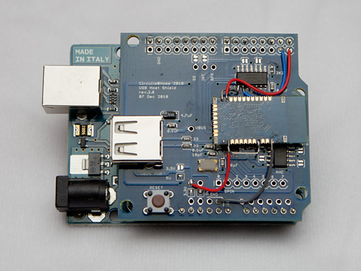
In this article I’ll show how to build Wireless EOS Controller designed by Manishi Barosee. I’m building it for my Canons and if I like it, I’ll see if it’s possible to modify it for other camera systems. My controller is built around full-size USB Host Shield instead of Mini which Manishi used – I’m going to do some debuggung and need space to connect probes. Also, full-size shield is much easier to work with.
The design of Yanis is simple yet elegant. It consists of Arduino board, USB Host Shield and serial Bluetooth module. An Arduino sketch reads the serial port, generates camera control commands and sends them to the camera over USB. The Android application acts as a UI for the controller and sends control data over Bluetooth. Here is very basic schematic drawing of Arduino part of the controller showing necessary connections. USB Host connections are described in hardware manual and Bluetooth module connections are shown in detail below.
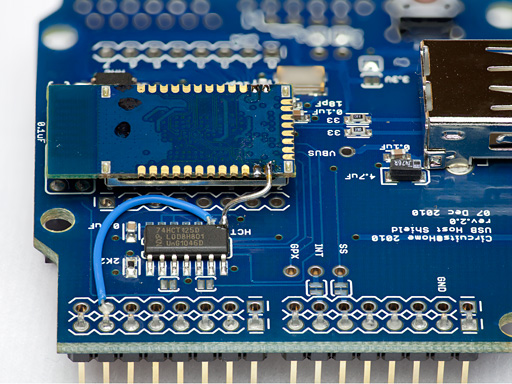
I’d like to start with radio link. The Bluetooth module used in this build is RN-42 from Roving networks. It is 3.3V device and its pins are not specified as 5V tolerant which means that Tx pin of standard 5V Arduino can’t be connected directly to Rx pin of [my] RN-42. Fortunately, the 5V to 3.3V level shifter on USB Host shield has 2 extra gates and I will be using one of them to “condition” the Tx. To do this, I need to cut ground trace going to pin 9 of D6 (marked ‘HCT’ on the PCB), connect it to Arduino pin 1 and then connect pin 8 of D6 to Rx of RN-42.
Picture on the left shows part of USB Host Shield PCB with light blue cross indicating the trace which needs to be cut. Care must be taken while cutting it as the rest of the pins on this side of IC must be left connected to the ground by horizontal trace and a via. Picture on the right shows pin 9 connected to Arduino Tx pin.
Next picture shows how I mounted the Bluetooth module. A piece of solid wire (a cut off resistor pin) is soldered to pin 8 of U6 and Rx pin of RN-42. It is pretty solid, however, if more secure attachment is desired, double-sided scotch tape can be placed between Bluetooth module and USB Host Shield PCB.
Once Bluetooth module is mounted, finishing the circuit is easy. As can be seen in the picture below, a wire is run from Rx pin of Arduino to Tx pin of RN-42. Also, 3.3V and ground are taken from Arduino to power Bluetooth module. Lastly, pin 4 of RN-42 is pulled up in order to force its serial port to initialize at 9600 baud at power-up. It is worth noting that bootloader won’t work when Bluetooth is connected to serial port – before loading a sketch USB Host Shield must be pulled off of Arduino.
Once circuit assembly is done it’s a good idea to test the radio once again using the same loopback idea I described in the previous post. At this time, the loopback will be provided in software. The following sketch sets serial port to 9600 baud and then reads symbols from the port and sends them back. The sketch can be copy/pasted from this page into Arduino IDE window. The test procedure is exactly the same as hardware loopback – run BlueTerm, connect to the Bluetooth module and start typing.
/* a loopback program - reads serial port and sends data back */ void setup() { Serial.begin(9600); } void loop() { while( Serial.available()) { uint8_t tmpbyte = Serial.read(); Serial.write( tmpbyte ); } } |
When radio functionality is confirmed, it’s time to load software into Arduino and Android. Links to the code are on the author’s page mentioned in the beginning of this post. I also made a variant of Arduino sketch compatible with current Android application – it is meant to be compiled with current revision of USB Host/PTP code but otherwise identical to the original one. The sketch can be downloaded from gitHub.
As I said in the beginning, I’m planning on expanding this controller to provide other functions an support other camera systems. In the meantime, build this controller, try it and let me know what you think.
Oleg.


hi,
i am using the same bluetooth as manis. i am using the arduino uno and full size USB host shield as well. do i need to do the same cutting steps? or can i directly connect to the 5V?
If your Bluetooth module is 5V you can connect it to serial pins of Arduino directly.
thank guys!
now i just cant wait for the other parts to arrive.
@Keith
The bluetooth module you are using is 5v tolerant. I will work.
*it.
hi,
i having error compiling. i have checked, these files are in folder of uhs2. why did it still say No such file or directory?
In file included from C:\Users\Keith\Desktop\arduino-0022\libraries\ptp2/ptp.h:26,
from yanis_ptp20.cpp:40:
C:\Users\Keith\Desktop\arduino-0022\libraries\ptp2/ptpdebug.h:22:33: error: ../USBHost/printhex.h: No such file or directory
C:\Users\Keith\Desktop\arduino-0022\libraries\ptp2/ptpdebug.h:23:32: error: ../USBHost/hexdump.h: No such file or directory
C:\Users\Keith\Desktop\arduino-0022\libraries\ptp2/ptpdebug.h:24:32: error: ../USBHost/message.h: No such file or directory
just to add on,
i did:
– download the usb host shield 2 and put into a “Uhs2” folder
– download the ptp 2 and put into a “Ptp2” folder
– download and unzip Time, TimeAlarms,DS1307RTC
– download “yanis_ptp2.0” and it is in a folder call yanis_ptp2.0 too.
– then put Uhs2, Ptp2, Time, TimeAlarms, DS1307RTC into \arduino-0022\libraries folder
is there any step i missing or file put into some wrong folder? been searching online for past few hours and cant get any clue. 🙁
thank for the help in advance!
yanis_ptp20 should come in examples/ directory of PTP2.0, you don’t need to download it. Try to rename Uhs2 to USBHost and see if error goes away.
ok, i finally figured it out.
it coz inside ptpdebug, the /USBHOST/… should be changed to /uhs2/
guess i was too excited to think properly. thanks anyway! gonna continue trying!
Hello i have already posted in topic “Testing RN-42 Bluetooth” on this site. I have without any errors installed arduino Yanis 2.0 code on arduino with no error (with libraries).
Then install Yanis EOS android application successfully no errors.
My hard setup is correct. Bluetooth Tx to Arduino Rx and other way round. But with no voltage regulation from 5v signal to 3v signal.
My camera is correctly connected. with usb cable, cable has been checked. Usb pin 1 from both sides have connectivity, same for other 4 pins. (I have 5pin micro usb both ends)
When everything turned, and android application correctly connected, I dont have the correct expossure settings of camera, CAPTURE button doesn’t work.
If i loop TX and RX on bluetooth, and connect with Android “Blueterm” application, it works by sendind back my letter i tapped on keyboard. Which meen that the bluetooth module can still receive and send back to my phone letters. So bluetooth is totaly fonctionnal.
Conclusion, my bluetooth can still fonction after having been connected to arduino tx and Rx pins which are 5v signal. Where are bluetooth apparently shouldn’t received tx/rx signals over ~3v.
So if my bluetooth is working, why doesn’t the whole system work?
Have i not correctly crossed out all possible errors?
Any ideas?
BlackHawk1793
Have you checked your camera yet? You can check it similarly loading say EOSRemote sketch and watch its output in BlueTerm via Bluetooth.
Hi, I have upload the code in the dongle, bluetooth is working (my android is connect to him) but in the app it say “Module connection error, Check that the selected device support SPP” What that does mean ?