|
|
By Oleg Mazurov  E strobe train
Traditionally, Toshiba HD44780-compatible alphanumeric LCD displays are driven by bit-banging bus signals combined with long delays between sending commands and data. In many cases this method is good enough. There are other cases as well where extra CPU cycles are not available and more economical method of driving a display is needed. I’m currently working on a design involving very fast USB exchanges combined with occasional LCD output and developed a solution which works very well for me. I’m posting it with hope that my fellow developers will find it useful.
HD44780 displays have been around for a long time. The internet provides plenty of posts about them, code samples and even a Wikipedia article. My favorite introductory text on the topic is Dincer Aydin’s LCD Info page.
PIC24 16-bit microcontrollers from Microchip have been around for some time as well. They are cheap and powerful and the Microchip C30 compiler (free version available) is quite good. They are not as popular as their 8-bit counterparts from Microchip and Atmel therefore good PIC24 resources are scarce. One nice introductory text on the topic can be found at Engscope.
Since I’m trying to minimize CPU time spent driving the LCD let’s first talk about timing in general. When developing for HD44780 we need to deal with 3 different times. First is the timing of the display part – the screen we see. LCD glass is very slow. When we attempt to update the screen faster than say twice a second the symbols become blurry and pale. The fastest display in my collection still looks OK when updated at 4Hz rate (250ms), while most others are twice as slow.
On the other hand, display data bus timing is many times faster. In order to write to the display we first need to set RS, RW and data lines, wait a little, then assert E line, wait some more and then de-assert it. If we are reading from the display we will also need to wait a little more after de-asserting E before we can read the data on the bus. Total bus cycle length is ~2.5us, which is 200 000 times less than the update rate of typical LCD glass. This time is pretty short but the MCU is still faster – a PIC24F clocked at 32MHz has an instruction cycle of 62.5ns and in 2.5us it will be able to execute 40 instructions. Therefore, no matter how simple it looks, it is preferable not to bit-bang the bus.
The third timing we need to deal with is command execution time. All but two LCD commands have stated execution time of 40us. Two slow commands – Clear and Home require 1.64ms to finish. Those are datasheet numbers, in reality the fast command on a modern display may finish in as low as 10us and slow commands on an old display can take as much as 3.5ms, depending on the age and the particular “HD44780-compatible” controller used. It is about 100 times faster than the glass.
Continue reading Driving a character LCD using PIC24 Enhanced Parallel Master Port
By Oleg Mazurov  Arduino reading digital scale
I am the proud owner of Stamps.com Model 510 5lb digital scale. It is a nice little scale which works very well (much better than Stamps.com service itself) while attached to my workstation. The scale doesn’t have a display making any kind of standalone use difficult. However, since the scale is a USB HID device reading data from it should be as easy as from a joystick and Arduino board should be adequate to provide a display function for it. To test this theory I made a simple setup consisting of Arduino UNO, USB Host shield and HD44780-compatible LCD display. I also wrote a small sketch which polls the scale and outputs the weight. The secondary objective of this project was to demonstrate LCD support in USB Host shield library.
For this project I used the following:
- An Arduino board. Standard size board, such as UNO, Duemilanove or Leonardo, will work
- USB Host Shield
- Toshiba HD44780-compatible LCD display, in 16×1 or 16×2 configuration. If you’re planning to use this sketch for something else, like data logging, the display is optional – all output from the scale is repeated to the serial port
- Stamps.com 5lb digital scale. Scales are standard HID devices with usage table 0x8d, therefore, scales from other brands may work as well with no or minimal modifications to the code
- USB Host library
The example code is also hosted at github, as well as in ‘examples’ section of the library under ‘HID’. It has been tested with Arduino IDE version 1.0.5.
In this project, the LCD is connected to the shield’s GPOUT pins, as documented in max_LCD.h header file. In addition to data lines, 5V and ground must also be connected to the shield’s 5V and GND terminals; the RW pin must be grounded – I do it on the LCD itself. In order to see the characters, the display must be biased – a 5K-10K pot with wiper on Vo and other two pins on 5V and ground will provide contrast adjustment.
Continue reading Adding a display to a digital scale using Arduino and USB Host shield
By Oleg Mazurov  Scanning barcodes using Arduino and USB Host Shield An addition of Human Input Device Class support to USB Host Shield library 2.0, announced several days ago allows using powerful and inexpensive input devices with USB interface in Arduino projects. Sample sketches demonstrating sending and receiving data to one of the most useful HID device types – boot keyboard/mouse, has been released along with the library. The beauty of boot protocol lies in the simplicity of device report – a data packet containing information about button presses and mouse movements. However, samples were designed to demonstrate all features of the class and because of that, they are somewhat heavy. In real-life applications, it is often not necessary to implement each and every virtual function – only what is needed. In today’s article I will show practical application of HID boot device building a simple gadget.
Originally, HID boot protocol was meant to be used with keyboards and mice. When USB became popular, other keyboard-emulating devices, such as barcode scanners and magnetic card readers have been migrated from PS/2 standard to USB while keeping their keyboard-emulating property. As a result, many modern “not-so-human” input devices behave exactly like a keyboard including boot protocol support. A gadget that I demonstrate today is portable autonomous barcode scanner built using Arduino board, USB Host shield, handheld USB barcode scanner and LCD display (see title picture). The operation is simple – when handheld scanner button is pressed, it scans the barcode and sends it to Arduino symbol by symbol. Arduino then outputs these symbols on LCD display. LCD is erased before outputting each new barcode by tracking time between arrival of two consecutive symbols. To keep the code simple, I intentionally did not implement any data processing, however, since Arduino sketch for the gadget compiles in just a little over 14K, there is plenty of memory space left for expansion.
Continue reading Connecting barcode scanner to Arduino using USB Host Shield
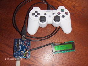
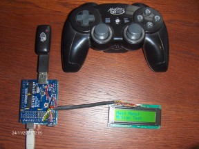
By Richard Ibbotson  PS3 controller connected to Arduino USB Host Shield Another HID example has been added to Github repository of USB Host Shield for Arduino (which you can purchase in my store) . Richard Ibbotson sent me this nice piece of code along with some pictures. He also posted a short description of his sketch in comments section:
I wrote a sketch for the interface of the PS3 controller over USB. I have two controllers, one Sony and one Madcatz wireless with a USB dongle. Both of these work fine to the USB host shield. I only made one minor change to the library to increase the NAK count. The sketch tests all the function, buttons, joysticks, accelerometer/gyro, leds and rumble. This is not yet under bluetooth just USB. I can set the host bluetooth adddress on the controller though which is needed for bluetooth pairing.
Did not make much attempt to reduce code or data size, so only have about 4K of program space and 240 bytes of data space left, but sketch is pretty long. The actual PS3 part is very small and could be made to a small library.
Next is to move to the bluetooth part, from what I have found on the direct USB, I am pretty confident this will fit even on the 168.
PS3 controller support opens some very interesting possibilities. Not only can it be used as a normal “joystick plus buttons” type of control, but you can also utilize it’s accelerometer/gyro. With wireless variant of the controller all kinds of very powerful radio control are possible. Who is going to be the first to make a mechanical dog, which follows you around and brings back the controller when you throw it away?
If you want to try the sketch, make sure you have the latest library code as well – there are some small but important changes made recently in NAK handling.
 MadCatz wireless controller to USB Host Shield |
 Wireless mini keyboard connected to USB Host Shield |
By Oleg Mazurov  USB Host Shield driving a keyboard
I am continuing on topic of using USB Host shield to drive USB peripherals started in the previous article. The code presented here performs keyboard polls, character translation and management of “LOCK” keys – NumLock, CAPSlock and ScrollLock.
A keyboard is hard to use if results of typing can’t bee seen, so my first step was to add an output device. Even though HD44780-compatible character LCD can be driven with Arduino pins, I wrote a little library which uses GPOUT port of MAX3421E for LCD control. This library is now a part of USB Host Shield repo on github. I used LCD high-level routines from official Arduino distro and developed low-level functions specific to MAX3421E hardware, as well as LCD initialization. Since function syntax and behaviour (and source code ) is identical to official LCD functions, the user manual is already written and can be found in the library reference by title LiquidCrystal. The only difference is in the constructor; since only 4-bit mode is possible and only one pinout is supported, Max_LCD constructor is not accepting any parameters. The pinout of LCD connections to GPOUT is given in the Max_LCD.h file; see also title image of this article.
Continue reading How to drive USB keyboard from Arduino
By Oleg Mazurov  HD44780 LCD display Introduction.
As time goes by, microcontrollers become more powerful, cheaper, and smaller. A typical micro of the past could have had 40 pins and no internal memory. On the contrary, modern J-series PICs are made with 96K program memory and 28 pins. We can drive a lot of peripherals with that amount of memory, however we are getting short on pins.
In this article I will show how to drive a parallel interface peripheral serially. A HD44780-compatible LCD module is good candidate – it is popular, inexpensive, and slow, so you won’t be losing any speed while converting parallel to serial. And you could even save some money using a micro with fewer pins.
Continue reading Interfacing LCD via SPI.
|
|


