Release candidate 1 boards has been received, built, tested, and came out green wire free – at last! I placed an order for a small batch with board house and expect PCBs to be available in a couple of weeks. I am making second call for beta testers – if you write code and/or blog, drop me a line with a link to your blog and your voltage preference for the shield – 3.3V or 5V. I have more 3.3V boards left from prototyping so naturally people requesting 3.3V boards will have more chances to get one.
Updated Eagle and Gerbers are available in Downloads section. If you don’t have Eagle, here is the PDF of the schematic. Please make sure you are not using scematic posted in one of the previous articles – there are quite a few changes.
In this article I want to give an overview of the board and it’s features. I’d like to start with most complicated part, which is power configuration. First of all, the USB core part of the shield (MAX3421E) requires 3.3V to function. Second, bus-powered USB peripheral requires 5V on Vbus. However, to use self-powered USB peripheral we only need to connect 3.3V to Vbus to be able to see speed-setting pullup resistors. Consequently, for digital camera control applications, shield can be mated with 3.3V Arduino (like Sparkfun‘s Arduino Pro) with no additional power supplies.
Another good carrier board for USB Host shield is Duemilanove. This Arduino has both 3.3V and 5V on board. 3.3V is derived from USB to serial converter so in order to get 3.3V when Arduino is disconnected from PC you will need to supply 5V to the converter via Arduino’s USB connector. Also, since Duemilanove is 5V board, logic level translators would have to be added. More about this later.
|
For cases where you only have one of the required voltages, 5V to 3.3V and 3.3V to 5V DC-DC converters are available. In my opinion, these converters should never be used and the best way would be to use carrier Arduino suitable for the task, i.e. 3.3V Arduino Pro for self-powered peripherals and Duemilanove for bus-powered ones; however, if you have reasons to use unsuitable Arduinos, converters will help you to get necessary voltage. In any case, you will never need both converters at the same time.
Picture on the left shows close-up shot of power configuration pins, situated right next to Arduino power pins. To get a voltage, connect two pads inside a rectangle with a piece of wire. I usually use cutoff pins from through-hole parts. This picture shows how 3.3V configuration looks like. |
|
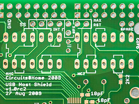
| Let’s now talk about control signals. Three SPI signals – SCLK, MOSI, MISO, are hardwired, the rest can be re-routed in case they are conflicting with other shields. Picture on the left shows how these jumpers look like – they are located close to Arduino’s D-pins. If default placement of control pins is OK, solder jumper wires between pads inside rectangles – this picture shows how. | |
| Another place, which needs to be tuned for particular board, is interface between Arduino and the shield. For compatibility with 5V systems, 2 logic level converters are routed close to control signal jumpers. They have to be populated with 74AHC125 on the left and 74HCT125 on the right. For 3.3V system, inputs of the converters has to be shorted to outputs, which is shown on this picture. | |
| Last connection which has to be made is Vbus. For self-powered peripherals it needs to be connected to whatever power is available. On the other hand, bus-powered peripheral would need 5V here. |
Other less significant parts of the shield are reset button, GPIO buffers and DC-DC converters. Reset button doubles one of Arduino board. GPIOs are equipped with level converters, which can be used to communicate with 5V logic. DC-DC converters were described earlier; like I said before, I consider them redundant. They were included in the design just because I had plenty of empty board space. If you are interested in these DC-DC converters, please take a look at the schematic and board layout files.
USB Host Shield is a more complicated than other Arduino shields and I’m hoping that this article will help you get familiar with it. If, after reading it you still have questions, please let me know.
Oleg.


