
Hantek DSO5000 screen
Some time ago I realized that I need to add digital oscilloscope to my set of instruments. DSO is handy for measurements and taking screenshots and this is what I have been doing a lot lately. After comparing specs of current models from several manufacturers I picked Hantek DSO5102B scope. The main reasons to choose this model were cost, screen size, and rich potential for hacking – in no particular order.
Hantek DSO5000-series scopes come in 3 bandwidth variants – DSO5062B(60MHz), DSO5102B(100MHz), and DSO5202B(200MHz). They are identical or nearly identical (early production scopes of different bandwidth had different value resistors soldered in analog front end but that’s the only difference), and making one from another is a simple matter of editing certain configuration files inside the scope. In addition to that, many other modifications can be made, including fan speed, low jitter ADC clock, low noise power supplies, and many others (see the EEVblog thread – the first link in the list at the end of this post). Newer benchtop DSO/MSO oscilloscopes from Hantek are based on the same hardware and there were successful attempts to make a MSO from this scope by adding a logic analyzer PCB.
As is often the case with Chinese products, the oscilloscope is also available under brand names Tekway, Voltcraft and some others with model numbers different from Hantek. The firmware has been originally developed by Tekway and uses Tekway model numbers – DST1062B(60MHz), DST1102B(100MHz), DST1202B(200MHz). Out of many brand names, Hantek seems to be the cheapest. Also, where I live (the US) Hantek can be bought locally. When I was shopping around, 60MHz models were more expensive than 100MHz so I ended up buying DSO5102B from Hong Kong for $388.88 shipped by UPS Global Express.
After receiving the instrument I checked the functionality. The scope worked well, the screen was large, and bugs were tolerable. I then proceeded to “modify” the device to 200MHz model; what follows is the detailed description of the steps I took to implement the mod outlined in EEVblog thread (Tinhead, you are the man!) – proceed at your own risk! The instrument has no “warranty void” stickers and I’m assuming that from the warranty standpoint opening the case is OK but I never bothered to actually check this assumption. In the worst case the instrument would have to be shipped to the seller/manufacturer for repair or replacement. Also, the procedure involves operating the device with power supply exposed – please be careful!
Step 1. Backup

100MHz risetime
First thing to do before making any firmware modifications is to establish known good state in case the mod is unsuccessful and a roll back is necessary. The backup is done to a USB flash drive. Download the Tools_B_models.zip archive, extract it and read how_to_backup.txt in Backup_B_models subdirectory. Then copy dst1kb_b_backup_tool.up file to an empty USB flash drive (128Mb or larger) and insert the drive to the USB connector on the front of the instrument. Wait for the floopy icon on the top of the screen to change color to blue, then press “UTILITY” button and then “F2”. Even though the function name is “Firmware Update” the file on the USB drive doesn’t update anything – we are making backup. Follow instructions on the screen, wait for backup to finish (it takes a while, don’t panic), then copy the contents of the flash drive to a safe place.
It is also a good idea to test the capabilities of the instrument before the mod. To do this I connected very fast pulse generator ( <100ps rise time ) to channel 1 of the scope and took following screenshot. fastest timebase setting is 4ns>Step 2. The Mod
As I mentioned, 60, 100 and 200MHz scopes are all the same; to change the bandwidth several files need to be modified. The scope runs Linux internally and serial console connection is available on the main PCB. In order to access it, I needed a) remove the case and b) pull the EM shield from the main PCB. The case can easily be removed by unscrewing 4 screws, two next to retractable front legs and other two under the carrying handle. Link #3 has pictures showing locations of the screws.
The shield is secured by 5 screws – 2 at the top and 3 at the bottom. After screws are removed the shield can be pulled off without much difficulty. With the screen facing away the input stages are on the left under another shield and the console connector is to the right of the input stages.
Since I was curious about my input stages I pulled the shield from them as well and took a picture. What I needed to know were values of certain resistors around the variable gain amplifier – see link #1 for detailed discussion.
The following picture shows the oscilloscope with the case and shield removed. A place where to look for console connector is pointed at with an arrow.

Console connector Location
Next picture is a closeup of the connector. My copy of the scope has this place populated with a pin header therefore connection is very easy. Positions of relevant signals are shown – they need to go to 3.3V USB to serial TTL converter (I used Sparkfun FT232R Basic Breakout). Note that Tx pin on the board must go to Rx pin of the converter and Rx pin on the board must go to Tx pin of the converter. This picture shows converter connected to the board.

Console Pinout
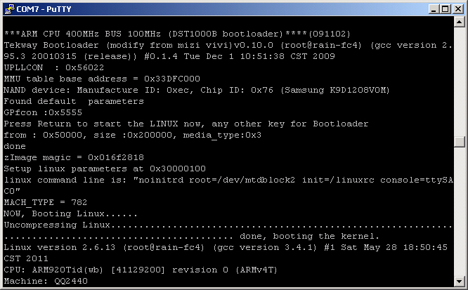
It’s now time to start hacking. A terminal session to the USB to serial converter’s COM port needs to be open – the serial port parameters for the terminal are 115200, 8N1. Then, the power must be applied to the scope. Again, be careful with exposed power supply! Because the instrument is lightweight it is difficult to plug anything into it with one hand. This is what I did: first, I made sure the power cord is disconnected on both sides, second, I pushed the power button in, and lastly, I connected the instrument end of the power cord, and then the other end – I’ve never even touched the powered device :-).
The oscilloscope will now start booting Linux OS. After some time, the output will stop; after pressing ‘Ctrl-C’ I got the following message:
Please press Enter to activate this console. |
which I did. After pressing ‘Enter’ I got a console prompt on the screen which looks like this:
[root@Tekway-dso /]# |
We are now in the root directory. Enter ls command. My (already hacked) root directory looks like this:
[root@Tekway-dso /]# ls OurLanguages fpgabank.conf lost+found tdc_edge125M bin help.db mnt tdc_overtime125M chk_base_volt home msg tdc_pulse125M cur_acq.type i2c.log mult_adc.log test dev icon nfs tmp disk_sta.info keyprotocol.inf opt tmpdst dn.rbf language.img param ubdb.swi dso lib proc usbsavefile.tmp dso.exe linuxrc protocol.inf usr dst1202b logo sbin var etc logotype sys.inf fpga.exe logotype.dis tdc.log [root@Tekway-dso /]# |
As can bee seen, the directory contains file named dst1202b – this is an indicator to the firmware to treat the hardware as 200MHz instrument. Lower-bandwidth instruments will have a file named dst1102b or dst1062b. The file itself is empty, only file name matters. First step of the hack is to change the name. The Linux command to do this (for 100MHz scope) is:
[root@Tekway-dso /]#mv dst1102b dst1202b |
Next step is to modify 4 files to contain the new name. The files are sys.inf, tmpdst, logotype, and logotype.dis. In the first three files, the ‘dst1102b’ needs to be changed to ‘dst1202b’, the fourth depends on a vendor, mine contained ‘hantek_DSO5102B’ and needed to be changed to ‘hantek_DSO5202B’. The vi editor is available, it is not very user-friendly so if you are not familiar with it I suggest reading the manual and practicing using it first on some other Linux system. In any of the files, only one symbol needs to be edited, so general sequence of keystrokes after opening the file is this: using the cursor keys, position the cursor under the character ‘1’ which needs to be changed to ‘2’, press ‘r’, then ‘2’, then ‘Esc’, ‘:’, ‘w’, ‘q’, and ‘Enter’.
After all files are changed, I simply rebooted my scope and enjoyed extra bandwidth. The following screenshot shows the same fast pulse that was used for baseline measurement – I now have 2ns timebase setting and ~1.8ns measured rise time.

Modified instrument maintains the “new” bandwidth after loading official firmware updates. This is just the first of many possible hacks – stay tuned!
Oleg.
Links to information about Hantek scopes describing this and other hacks:
- Tinhead’s EEVblog thread containing current information about the mods
- Das Oszi project page
- Uwe Hermann’s page
Thank you for this posting.
I just bought a Hantek DSO5072 70MHz. The BW is fine for me now, but I am interested in:
– instrument drivers for USB control (LabVIEW or DLL)
– activating FFT spectrum in the firmware
Can you help with either of these.
AFAIK this one is not modifiable. Check the eevblog thread linked to in the article.
AgentGG
regards labview drivers, the SDK i published in here
http://www.mikrocontroller.net/articles/Hantek_Protokoll
can be used to access your DSO. A good example how it works is that DSO Tool
http://peter.dreisiebner.at/dso-usb-tool/
These DSO5072P models are new and i had no chance to play yet with them, it seems lot of people bought them on ebay but nobody really contacted me.
All i know for now is that:
– bandwidth can be hacked
– my backup tool is not working (need to be recompiled on Linux 3 and for the
new SoC, yes there is complettly different SoC/new PCB)
– that there is not FFT is new for me (huh, this need to be hacked!!)
However, i can’t help or do anything without help from “P” model DSOs owners,
i need some manual files, etc.
The best will be when you contact me on eevblog forum
tinhead
Will this modification working for the DSO5101BM too?
Meaning DSO5102BM not 01BM…
HAve you studied the 5100 D series ( 5102d, 5202d) the HAntek DSO’s with built-in 16 channel logic analyzer? the also come in 60-100-200 mhz configs and should be similar to the previous models already hacked? Any new info on these new models?
The eevblog thread linked in the article has info on these.
There’s (probably newer) model named DSO5102P. I think I’ll go with it and buy it. Do you know if this one’s hackable too?
Regards,
Venci
Check the thread at eevblog.
Значит если купить DSO5072P то его улучшить и проапгрейтить нельзя будет?
И надо покупать DSO5102P, что бы можно было бы его улучшить?!
I have a DSO-5200A USB oscilloscope. It operates with Windows XP. I want to use it with a laptop which has Windows 8.1. Is there anything I can do to make this happen?
Thank You
Dave Davis
if you want a more permanent solution for access to the uart, previous hack projects on similar oscopes have been documented:
http://elinux.org/Das_Oszi_3.5MM_Uart
the full documentation for the hacks on hantek stuff can be found here:
http://elinux.org/Das_Oszi
Hello all. It is possible to hack this DSO from Windows 7? I`m not familiary with linux :(. If is possible, maybe a tutorial will be great.
Thanks and Regards,
Marius.
All,
I bought a Hantek DSO5102P (100Mhz), but what surprised me is that: its Horiz time base can reach to 2ns!! I assumed that I should get 4ns, this is not the end of the story, I applied 175MHZ signal, It detected it and read it as well, then 200MHZ, the same result up to 220MHZ.
Any explanation!!!
Cheers
Eid
hi
even I bought the dso5102p on Febrary 2015 and the minimun time base is 2 ns !! the firmware version is 3.40.0; tomorrow i will compare the scope respect a 4Ghz analog scope Agilent into my laboratory to understand the limit.
Hi Gianluca,
what was the result of your comparison?
========
I just bought the DSO5072P and I would like to extend it to 200Mhz.
Does already sombody know if the description above works for my model, too?
I’ll need to get the USB to Ser Converter first.
By the way:
SW 3.40.0 (140925.0)
HW 1000xfff8108