Recently, I was researching low-noise DC-DC converters and while reading Linear Technology Application Note 70 found this clever and useful circuit, designed by Jim Williams. The idea is to sense current in power inductor of the converter with another inductor, placed within short distance from the first one. The sensing inductor is connected to a circuit which amplifies and conditions the signal and generates nice clean square wave pulses which can be used to trigger oscilloscope sweep. The probe is isolated from the circuit preventing measurement corruption. As a bonus, analog output of probe amplifier allows observing current waveform through power inductor.
As is often the case with application notes, circuit description and build details are somewhat brief; I’m posting my notes hoping that the information will be helpful for other builders. Also, since BatchPCB doubled my order, I have extra PCBs; if anyone wants to build this circuit on a professionally made PCB with just couple green wires, e-mail me – the PCB can be yours for the price of postage.
To get detailed information about the circuit operation please read the application note. Circuit description starts at page 37.
Some parts used in the original circuit are hard to impossible to find. J.W. Miller #100267 inductor specified in the application note is no longer available. I tried several different 1mH inductors – they all worked. My favorite one is Xicon 434-1120-103K, available through Mouser. The axial construction makes it easy to solder to a cable and it can also be conveniently placed inside a piece of copper pipe to make probe more directional.
CA3096 transistor array was discontinued long time ago. I substituted it with Fairchild FMB3904 and FMB3906. While not a matched pairs, they perform well. Philips makes pin-compatible matched variant of those parts, I’m planning to try it in next revision of the board to see if it makes any difference.
I also made some minor changes to the schematic, mostly to clarify things. Project files are available from downloads section. This is a preliminary version – I’m planning to re-route the board to make it easier to fit on oscilloscope’s external trigger connector. As you can see on a title picture, analog out (lower left BNC connector, the shiny one) is unusable unless external trigger input connector is placed in the corner of oscilloscope’s front panel, like on this Tektronix 475A.
Also on a title page you can see probe compensation box. Luckily for me I had one from old times – the new ones, available from several parts distributors are ridiculously expensive. Buying old probe from eBay and cannibalizing it for its comp box would be much more economical. Don’t expect using the cable attached to the comp box though since it’s not a regular coax and won’t work. Another good source for small metal boxes with BNC connectors is used RF measurement equipment section on eBay.
Last piece of the setup – power to the amplifier, can be provided in many ways. The easiest is to utilize 5V provided by Tektronix oscilloscope probe power connector. Wall warts work well too.
Using the probe is simple. First, connect analog output to 50ohm oscilloscope input with attenuator set to 0.5V/div and digital output to oscilloscope external trigger input. Place probe inductor in the vicinity of the power inductor and observe current waveform. Adjust spacing to get good peak-to-peak amplitude without clipping. Check your digital output – you should see 5V p-p square-wave signal in phase with input signal crossing the midpoint. You now can use the digital output to trigger the ‘scope while observing output noise of the converter ( which, if your converter is good is too weak and fuzzy to give a good trigger ).
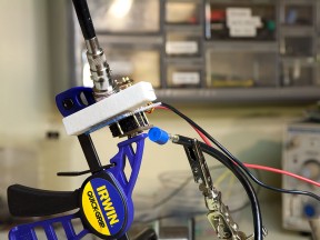
The probe is quite sensitive. Picture to the left shows typical placement. Little test fixture clamped in the Irvin clamp holds a DC-DC converter. The probe is placed on the right – it’s blue 1mH inductor held in alligator clip. The power inductor is on the left side of the converter’s board. The distance is about 1.5cm and circuit performs very well; in fact, this is the closest distance when probe signal passes first stage without clipping. It has to be noted also that the power inductor is of pot core variety and therefore radiates very weak field.
Of course, the probe amplifier can be used to condition not only inductor output but any other signal which won’t overload the input stage. Upper frequency limit is approximately 120MHz. I highly recommend building this circuit and playing with it – it is a useful aid to many common types of oscilloscope measurements.
Oleg.


Q. Have you seen the probes at http://www.bcarsten.com/?page=hfield
yes
I think this is _brilliant_ and I have been looking for this information. Thank you thank you. Please do not delete this design or the files that go with it. I don’t think that too many other folks are working on such a specialty application and have taken the time to read what Jim Williams has created. I really appreciate the work you have done to implement this design.
Chris Dot Tolleson At mac with com.
Please take a look at this post as well -> https://www.circuitsathome.com/dc-dc/magnetic-probe-amplifier-final-board-design . The layout is better and you can also order a PCB.
Hi Oleg
Thanks for introducing me to this type of sniffer and the Ap Note.
I am looking at the picture and the blue 1mH used as the sensing device. Firstly that coil is now end of life obsolete so I don’t know how long it will be available.
2’nd the coil is unsheilded. In Jim’s Ap Note he has the coil inside a shielded copper tube. What is the significance (and importance) of that and also can you explain how he cuts the slit in the tube.
Regards MArtin at Afimilk
There are other inductors that can be used. I don’t think the slit is necessary, not in this type of probe anyway.