Quadrature rotary encoders, also known as rotary pulse generators, are popular input devices for embedded platforms, including Arduino. Several rotary encoder code examples are posted on Arduino site and elsewhere, however, they treat encoder as a pair of switches, adding decoding/debouncing overhead. For many years, I used an algorithm based on the fact that quadrature encoder is a Gray code generator and if treated as such, can be read reliably in 3 straight step without need for debouncing. As a result, the code I’m using is very fast and simple, works very well with cheap low-quality encoders, but is somewhat cryptic and difficult to understand. Soon after posting one of my projects where I used rotary encoder to set motor speed i started receiving e-mails asking to explain the code. This article is a summary of my replies – I’m presenting small example written for the purpose of illustrating my method. I’m also going through the code highlighting important parts.
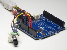
The hardware setup can be seen on title picture. The encoder from Sparkfun is connected to a vintage Atmega168-based Arduino Pro. Common pin of the encoder is connected to ground, pins A and B are connected to pins 14 and 15, AKA Analog pins 0 and 1, configured as digital inputs. We also need a serial connection to the PC to receive power, program the Arduino, and send program output to the terminal. For this purpose, Sparkfun FTDI basic breakout is used.
Connecting encoder pins to pins 0 and 1 of 8-bit MCU port makes encoder reading code very simple. If analog pins are needed for something else, it is possible to move encoder to digital pins 8,9 or 0,1 (losing serial port) with no modification of code logic. While technically using any two consecutive port pins is possible with a bit of tweaking, using non-consecutive pins for encoder input with this method is not recommended. Lastly, it sometimes hard to determine which encoder pin is A and which is B; it is easier to connect them at random and if direction is wrong, swap the pins.
