Posts

Repairing Tektronix S-6 sampling head

While making some measurements today I noticed a strange reflection in the signal generated by my Tektronix 7S12 TDR sampling plugin. At first, it looked like a bad connection at the output of the loop-through S-6 sampling head, however, after further testing it turned out to be more serious flaw. The following two screenshots show the reflection: the left one shows the step into terminated S-6 and the right one shows the same step with terminator removed to give me the reference for the distance. Apparently, the reflection occurs inside the head itself!

Reflection with upper connector terminated by 50 ohms

Reflection with upper connector terminated by 50 ohms

Reflection with termination removed

Reflection with termination removed

S-6 sampling head disassembled

S-6 sampling head disassembled


I pulled the head out and took it apart. It was rather easy – after removing 3 screws on the back the head internals slide forward from the case. The picture on the right shows the guts of the sampling head with preamplifier board removed. The square metal box next to the faceplate with two SMA females sticking out of the back is a hybrid sampling bridge and according to the distance to the reflection this is the place where I need to look.

Further disassemby is easy. First, 3 socket head screws need to be removed along with the board they are holding. After this is done, both male SMA connectors need to be unscrewed. Lastly, after unscrewing two nuts on the faceplate the bridge can be freed from all obstacles and taken apart.

S-6 sampling bridge

S-6 sampling bridge

Luckily, taking the hybrid apart was not necessary this time. I discovered that one of SMA connectors (upper left on the picture) came loose so I simply tightened it up, assembled the head, placed it back into 7S12 and observed a nice step with good corners and no extra reflections. The whole project took less than an hour, most of the time spent taking pictures.

I’m a happy time-domain reflectormetrist again, writing this article hoping it will be helpful for someone. Next time your sampling head starts acting funny don’t run to eBay for the new one (and I checked – they are out of S-6 at the moment). Take it apart and look inside – you may be able to fix it, even though in my case it was more by luck than judgement.

Correct step waveform

Correct step waveform

Adjusting inverter control in Tektronix 7104 oscilloscope power supply

Access to 109V test point

Access to 109V test point

In this short article I want to share a trick that I learned today while checking the power supply of my trusty Tektronix 7104 oscilloscope. Step A2 of calibration section of the manual calls for measuring/adjusting of pre-regulated 109V voltage on TP1326 test point. Typically, test point access for this step requires removing power supply cover which takes time and exposes high voltages. The test setup presented on a title picture( click on it to make it bigger) shows how to access this test point leaving power supply cover in place.

The power supply cover is at ground potential so don’t try to reach the test point with non-insulated probe. I used Tektronix Klip Chip IC probe threaded through nearby ventilation hole to grab the test point post. The post is clearly seen through a larger hole, through which an adjustment potentiometer R1293 is usually accessed. A flashlight is handy.

Next picture shows the closeup of the test connection. A test probe is supported by a “Third Hand” thingy – I wanted to observe voltage fluctuations in the course of two hours to make sure it stays within limits.

I’m hoping this trick will be useful for somebody dealing with similar power supply.

Oleg.

Repairing front panel buttons of Tektronix 7904 oscilloscope.

Front panel interconnect board of Tektronix 7904

Front panel interconnect board of Tektronix 7904


I am a proud owner of several Tektronix 7000-series mainframes. Among them, 7904 500MHz 4-compartment oscilloscope is my bench workhorse. The screen is big enough, the bandwidth is adequate for majority of tasks I do, and absence of cooling fan makes it pleasantly quiet. In addition, the instrument is lightweight comparing to other 7000 mainframes and has legs mounted on the rear panel making it possible to put scope on the floor in a vertical position.

I became annoyed by malfunction of right buttons of both vertical and horizontal mode selectors (they failed to lock in place) and decided that my scope deserves some TLC. Besides fixing the buttons I also wanted to replace some dead illumination bulbs with LEDs. Mode switches are dual, with one switch in the pair dedicated to turning light bulb on/off. Bulbs are powered by 5V and dimming is implemented by means of two diode drops. So the 3V LED restricted to 10ma by a resistor shall work fine and even be able to dim a little. In addition, LED power is comsumption about 8% of a bulb.

The front panel buttons are mounted on a narrow PCB (called “A3- Front Panel Interconnect Board” in the service manual) running across the middle of the front panel. It can be easily accessed after removing side panels. There are several cables connected to the board on both sides, it is good idea to mark them before disconnecting. The title picture shows left side of the board (one close to horizontal bay “B”) with my marks on it. After pulling out cables I moved the PCB carefully towards the rear and to the side. The board bends easily and is somewhat accessible form the top of the instrument.

The button assembly is held in place by screws also used to mount upper plug-in guide bars in the plug-in compartment. Picture below shows location of the left ones (holding vertical mode buttons). After unscrewing four Phillips-head screws I pulled the vertical mode buttons out of the chassis, carefully guiding it around cables, structural members and dead mice.


Continue reading Repairing front panel buttons of Tektronix 7904 oscilloscope.

Spring cleaning of AM503.

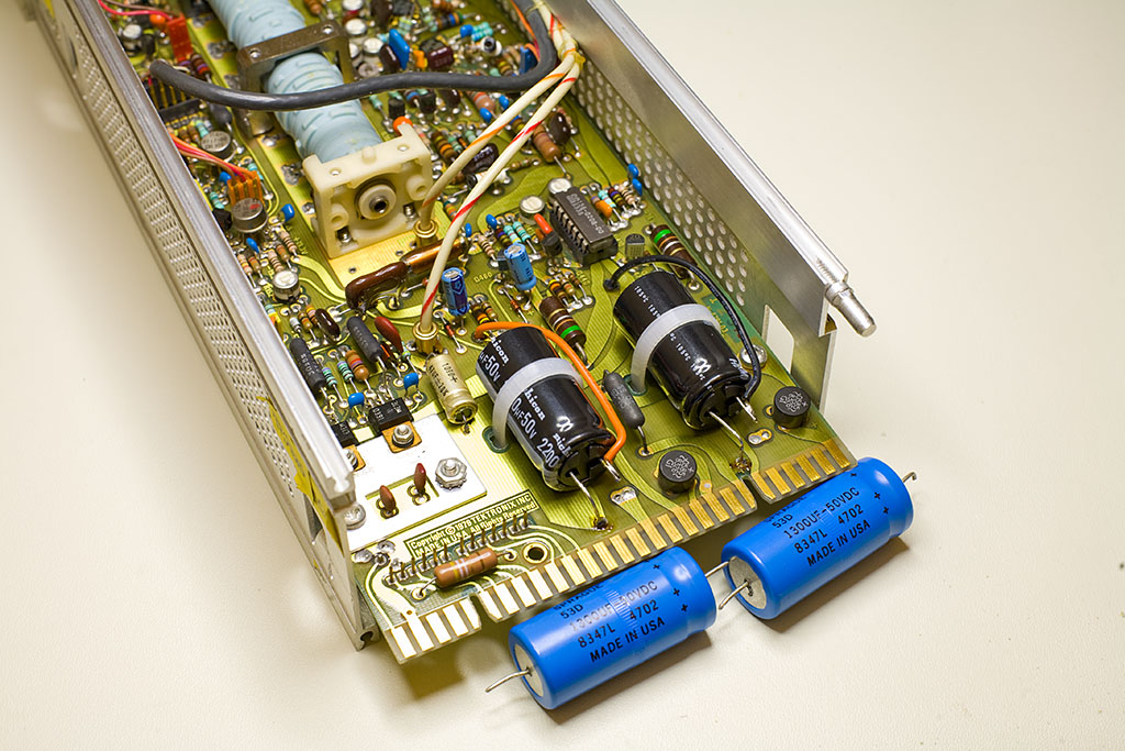
AM503 with replaced capacitors

AM503 with replaced capacitors


The single most valuable instrument in my possession is Tektronix current measurement system, which consists of AM503 probe amplifier with accompanying A6302 AC/DC probe. While probe itself doesn’t need much attention besides occasional wiping the dirt off the jaws, the amplifier recently became quite noisy in several attenuator positions so I decided to give it a good spring cleaning.

I adopted the procedure described on a web site dedicated to restoring Tektronix oscilloscopes; the guy was talking about fixing fuzzy trace by cleaning input attenuator contacts of Tek475. I am unable to find this site anymore; if anyone knows the link, please let me know so I can give him proper credit.

The places in need of cleaning are attenuator contacts and range resistors R206, R208, R212, R214, as well as terminating resistors R204 and R216. For cleaning I use Deoxit from Caig Laboratories and a piece of clean printer paper. A match or a toothpick could be helpful in tight places; don’t use anything metal though; you don’t want to scratch your old Tektronix gold.


Continue reading Spring cleaning of AM503.