|
In previous article I started talking about constructing magnetic stirrer from PC fan, a pair of rare earth magnets, and plastic can. In this article I will show the rest of the construction as well as program code to control the motor.
When building cases for my designs, I tend to avoid techniques requiring accurate (read “any”) measurements and calling for non-round holes. The design that I’m describing here is no exception. In order to complete it I needed just a few extra parts in addition to plastic joint compound can, PC fan and magnets, arrangement of which was described earlier. I used Arduino controller equipped with Motor Shield from Adafruit to supply PWM current to the fan, 3 nylon standoffs with adhesive bottoms to mount Arduno, rotary encoder to set stirrer speed, and panel-mounted 2.1mm DC power jack. The stirrer is powered from 12V wall wart capable of supplying 300mA or more. I was thinking of implementing monitoring of motor current to track the moment when stirrer bar loses attraction to the magnets and stops rotating. When I was playing with the stirrer powered from bench suplly the change in current was quite visible. However, I found out later that when motor is supplied with PWM signal, current stays almost constant over the whole range of duty cycles and loads and current tracking won’t work. With regret, I abandoned this clever feedback idea. On the bright side, the code necessary to control the stirrer immediately became much simple, short and easy to understand. |
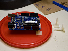
| Finishing mechanical build is simple. First, Arduino is mounted on the lid of the can as shown on the picture to the right. If you decide to build the stirrer like I did, try to position Arduino as close to the edge of the lid as possible, otherwise you’ll have difficulties fitting power plug. However, you can’t place it too close as the can is conical and would interfere when placed on top of the lid. The trick to find the right place is to fit standoffs to the board, mount motor shield on top of Arduino, place the thing close to the circular ridge of the lid, then carefully position the can in place and then take it off. Arduino will be pushed in the right spot, you will then need to mark around standoffs and attach them. | |
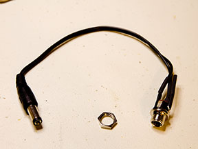
| Power adapter is made from panel mounted female barrel connector soldered with short cable to male piece cut from a dead wall wart. The space inside the can is tight; cable relief on male connector has to be trimmed in order for it to fit. Right angled connector is even better, if you can find one. | |
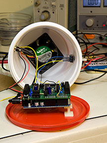
| This is final arrangement. Motor shield sits on top of Arduino, fan is attached to PWM channel 2, rotary encoder pins A and B are soldered to analog pins 0, 1, common pin is grounded. Two round holes are drilled on opposite sides of the can to house female power connector and encoder. Cable relief on male power connector is trimmed. It’s now time to take a look at the code. |
The sketch is posted below. It is a simple control loop, which changes PWM duty cycle with encoder rotation. It also outputs “encoder count” out on a serial terminal for debugging purposes. Interesting parts of the code (both of them) are commented after the listing.
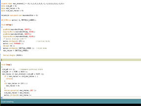
1 2 3 4 5 6 7 8 9 10 11 12 13 14 15 16 17 18 19 20 21 22 23 24 25 26 27 28 29 30 31 32 33 34 35 36 37 38 39 40 41 42 43 44 | #define encoder0PinA 14 #define encoder0PinB 15 #define INITIAL_SPEED 70 #include <afmotor.h> signed char enc_states[] = {0,-1,1,0,1,0,0,-1,-1,0,0,1,0,1,-1,0}; byte old_AB = 0; byte enc_value = 0; byte old_enc_value = 0; AF_DCMotor motor( 2, MOTOR12_64KHZ); void setup() { pinMode(encoder0PinA, INPUT); digitalWrite(encoder0PinA, HIGH); pinMode(encoder0PinB, INPUT); digitalWrite(encoder0PinB, HIGH); /* motor startup code */ motor.setSpeed( 255 ); //initial kick motor.run( FORWARD ); delay( 50 ); motor.setSpeed( INITIAL_SPEED ); //slow down enc_value = INITIAL_SPEED; Serial.begin (9600); } void loop() { old_AB <<= 2; //remember previous state old_AB |= ( PINC & 0x03 ); enc_value += enc_states[( old_AB & 0x0f )]; if ( enc_value == old_enc_value ) { return; } if( enc_value == 255 ) { enc_value = 0; } Serial.println( enc_value, DEC ); old_enc_value = enc_value; motor.setSpeed( enc_value ); } |
Lines 20-23 provide motor startup. First, duty cycle is set to 100%. Then, after 50msec PWM is set to “slow”. This allows reliable start in difficult cases.
Encoder polling is implemented on lines 32-34. Results of all possible transitions are contained in array enc_states. Current state is read, previous is shifted to upper part of a nibble, which serves as array index, and encoder count is ( or is not ) updated. This technique saves program space and eliminates the need for encoder debouncing by excluding illegal combinations.
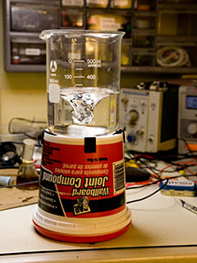
The code is written , compiled and loaded into Arduino. The can and its lid are joined together. The last picture shows the device after a pair of final touches – pieces of foam rubber placed on top of the stirrer and little rubber legs which came with Arduino (Adafruit exclusive, other shops won’t include legs with Arduinos) are attached to the bottom. The stirrer is now complete.
In the next couple of days I’m planning to produce a video showing my stirrer’s enormous power. While completed, it will be posted here.
As usual, questions or comments about this project are most welcome.
Oleg.
[…] This post was mentioned on Twitter by KnurdStuff. KnurdStuff said: Vigorius stirring redefined. Part 2 – electronics.: In previous article I started talking about construct.. http://bit.ly/UPFx […]
Maybe you could use the tacho-signal to track the moment where the stirrer stops spinning. I would expect the rpm to go up if the motor is running freely.
Thank you for the idea – I will surely try this!
Neat stuff, Oleg!
I’m trying to borrow your encoder routine to use in my PIC 18F4620… I’ve got a couple of questions, though.
In line 33, you AND PINC & 0x03, and then OR it with old_AB… what is PINC connected to? How to you get your encoder0PinA & B input values into enc_value? (I’m guessing here…)
Thanks for a great website and projects!
I guess what I’m asking is, how do you read your encoder?? (Like you said, outputting the question clariefies it in your mind!)
Encoder’s A and B pins are connected to Atmega’s PORTC pins 0 and 1. The name for the whole port byte is PINC. The magic happens on line 33 :-). ‘PINC & 0x03’ clears upper 6 bits of whatever was read from PORTC leaving bits 0 and 1 intact. ‘old_AB |= ( PINC & 0x03 )’ generates an index for enc_states. This code would work on a PIC with almost no changes, the port name being the only one. You would need to have your encoder connected to 2 lower bits of a port, otherwise the code would become more complex.
Oleg, yours is the most elegant and simple code for reading an encoder I have seen… only it doesn’t work for me! Would you mind looking over what I have here and possibly giving me a suggestion?
#include

#fuses HS,NOWDT,NOPROTECT,NOLVP,BROWNOUT,PUT,NOPBADEN,DEBUG

#use delay(clock=20M)

#use rs232(baud=115200,parity=N,xmit=PIN_C6,rcv=PIN_C7,bits=8)

#include
signed char enc_states[] = {0,-1,1,0,1,0,0,-1,-1,0,0,1,0,1,-1,0};
byte old_AB = 0;
byte enc_value = 127;
byte old_enc_value = 0;
void encoder0Loop(void) { // int8 enc_value
old_AB <<= 2; //remember previous state by shifting the lower bits up 2
old_AB |= ( portb & 0x03 ); // AND the lower 2 bits of port b, then OR them with var old_AB to set new value
enc_value += enc_states[( old_AB & 0x0f )]; // the lower 4 bits of old_AB & 16 are then the index for enc_states
if ( enc_value == old_enc_value ) {
return;
}
if( enc_value == 255 ) { // Original line
enc_value = 0;
}
printf("enc_value = %3d, old_AB = %3d, old_enc_value = %3d\n\r",enc_value,old_AB,old_enc_value); // debugging...
printf(lcd_putc,"\fEncoder 0 = %d\n",enc_value);
old_enc_value = enc_value;
// set whatever variable you need to increment to enc_value here...
}
//////////////////////////////////////////////////////////////////#int_TIMER0
void timer0_isr()
{
output_toggle(PIN_A2); // let me know it's alive...
}
//////////////////////////////////////////////////////////////////
void main(void) {
port_b_pullups(true);
setup_adc_ports(NO_ANALOGS);
set_tris_b(255);
input_b();
ENABLE_INTERRUPTS(global);
ENABLE_INTERRUPTS(INT_TIMER0);
SETUP_TIMER_0(RTCC_INTERNAL | RTCC_DIV_32);
printf("\n\r\rRotary Encoder Test 2\n\n\r");
printf(lcd_putc,"\fRotary Encoder\nTest 2");
delay_ms(1000);
while (true)
{
encoder0Loop();
} // end of while loop
} // end of main
I have scoped the encoder and it is working properly; currently this runs through the loop endlessly, with no response to the encoder at all! Any help would be greatly appreciated, but no problem if you don’t want to!
Thanks,
Brad
After a bit of twiddling I got it working – Oleg, I have to say that this is THE most elegant rotary encoder solution I have seen. I have spent the past week or so working with different routines for quadrature encoders and this is just absolutely awesome.
Thanks very much!
Brad
Somehow your previous post with code ended up in spam folder and I haven’t noticed it until today. Anyway, It’s nice that you had encoder control sorted out!
I really like the simplicity of this code and I want to use it in my project, but I’m running into a problem. My encoders are 624 counts per revolution but the code seems to max out at 255 even if I change the :
if( enc_value == 255 ) to if( enc_value == 624 ) .
I even tried changing from PINC to PINB thinking that the analog pins were maxed at 255.
Thanks,
Cory
If you want your enc_value to be larger than 255, it needs to be declared as unsigned int. It’s currently declared as byte AKA unsigned char which is 8 bits.
Duh! I should have known that lol
Thanks again,
Cory
[…] cheap low-quality encoders, but is somewhat cryptic and difficult to understand. Soon after posting one of my projects where I used rotary encoder to set motor speed i started receiving e-mails asking to explain the […]