Posts

Rotary encoder interrupt service routine for AVR micros

Encoder ISR

Encoder ISR


About a year ago, I posted an article about 2-channel rotary encoder interfacing with MCU using lookup table. With its linear program flow, inherent noise immunity and small processing requirements, this method produces extremely efficient code. The article attracted quite a bit of attention with many interesting comments and several code modifications. Today, I want to demonstrate slightly different way of reading the encoder – via interrupt service routine (ISR).

I’m currently involved in a project built with QP Event-Driven Real Time Framework running on 8-bit AVR micro. Rather than implementing periodic polling, I wanted to generate encoder events as they occur. AVR Atmega, as well as many other micros have external interrupt source called “Pin Change”, ideally suited for an encoder. As the name implies, pin change interrupt occurs when certain digital port pin changes state from low to high or vice versa. When an encoder is rotated, one pin changes state from say low to high, then other goes from low to high, than the first one goes from high to low, then the other one goes from high to low. The cycle then repeats. In order to properly react to every state change we want to be able to generate interrupt on every transition on each pin and that is exactly how pin change interrupt works.

I am developing for custom built AVR-based board and all code snippets are pasted directly from project files. This code can be used on bare metal Atmega as well as Arduino board with no changes and can also be adopted for other micros with only minor modifications, such as port and pin names. Encoder’s A and B pins are connected to Port B pins 0 and 1, common pin is connected to ground. To prevent floating inputs, internal pull-ups are turned on.


Continue reading Rotary encoder interrupt service routine for AVR micros

Reading rotary encoder on Arduino

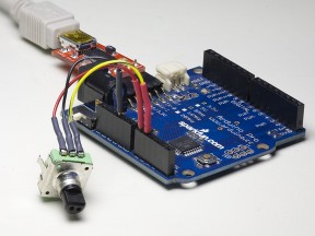
Rotary encoder connected to Arduino

Rotary encoder connected to Arduino


Quadrature rotary encoders, also known as rotary pulse generators, are popular input devices for embedded platforms, including Arduino. Several rotary encoder code examples are posted on Arduino site and elsewhere, however, they treat encoder as a pair of switches, adding decoding/debouncing overhead. For many years, I used an algorithm based on the fact that quadrature encoder is a Gray code generator and if treated as such, can be read reliably in 3 straight step without need for debouncing. As a result, the code I’m using is very fast and simple, works very well with cheap low-quality encoders, but is somewhat cryptic and difficult to understand. Soon after posting one of my projects where I used rotary encoder to set motor speed i started receiving e-mails asking to explain the code. This article is a summary of my replies – I’m presenting small example written for the purpose of illustrating my method. I’m also going through the code highlighting important parts.

The hardware setup can be seen on title picture. The encoder from Sparkfun is connected to a vintage Atmega168-based Arduino Pro. Common pin of the encoder is connected to ground, pins A and B are connected to pins 14 and 15, AKA Analog pins 0 and 1, configured as digital inputs. We also need a serial connection to the PC to receive power, program the Arduino, and send program output to the terminal. For this purpose, Sparkfun FTDI basic breakout is used.

Connecting encoder pins to pins 0 and 1 of 8-bit MCU port makes encoder reading code very simple. If analog pins are needed for something else, it is possible to move encoder to digital pins 8,9 or 0,1 (losing serial port) with no modification of code logic. While technically using any two consecutive port pins is possible with a bit of tweaking, using non-consecutive pins for encoder input with this method is not recommended. Lastly, it sometimes hard to determine which encoder pin is A and which is B; it is easier to connect them at random and if direction is wrong, swap the pins.


Continue reading Reading rotary encoder on Arduino

Vigorius stirring redefined. Part 2 – electronics

In previous article I started talking about constructing magnetic stirrer from PC fan, a pair of rare earth magnets, and plastic can. In this article I will show the rest of the construction as well as program code to control the motor.

When building cases for my designs, I tend to avoid techniques requiring accurate (read “any”) measurements and calling for non-round holes. The design that I’m describing here is no exception. In order to complete it I needed just a few extra parts in addition to plastic joint compound can, PC fan and magnets, arrangement of which was described earlier. I used Arduino controller equipped with Motor Shield from Adafruit to supply PWM current to the fan, 3 nylon standoffs with adhesive bottoms to mount Arduno, rotary encoder to set stirrer speed, and panel-mounted 2.1mm DC power jack. The stirrer is powered from 12V wall wart capable of supplying 300mA or more.

I was thinking of implementing monitoring of motor current to track the moment when stirrer bar loses attraction to the magnets and stops rotating. When I was playing with the stirrer powered from bench suplly the change in current was quite visible. However, I found out later that when motor is supplied with PWM signal, current stays almost constant over the whole range of duty cycles and loads and current tracking won’t work. With regret, I abandoned this clever feedback idea. On the bright side, the code necessary to control the stirrer immediately became much simple, short and easy to understand.

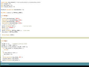
Stirrer code

Stirrer code


Continue reading Vigorius stirring redefined. Part 2 – electronics