|
|
By Oleg Mazurov  Blue Arduino USB Host Shield tied to telephoto lens mount Developer Si Li shared his version of PTPDevinfo.pde, which fits into older Aduinos. Si wanted to get PTP device information from Canon EOS 500D, but he only has 16K Seeduino at hand. So he stripped devinfoparser off all unnecessary strings leaving only ones essential for parsing Canon EOS camera device info.
The modified devinfoparser files are available from “Downloads” section.
By Oleg Mazurov  A reel of ADuM4160s
I’m pleased to announce that the long wait is finally over – I’m now in possession of a reel (this is 1000 pcs!) of ADuM4160 – the core chip of USB Isolator. I will be shipping back orders today and tomorrow – if you have ordered any of USB Isolator products from me in February, March, or April, and will not have gotten shipping notification by Monday, please contact me.
USB Isolators are back in stock. By popular demand, I also started selling ADuM4160 in single quantities – look in components section of the store.
On a side note, I received an e-mail from a company in Denmark offering ADuM4160-based USB Isolators in “complete” form – sporting a nice looking case and bus-powered supply for the peripheral side. I bought one yesterday to take a look. I’m going to write a review and, if I like it, start reselling it.
Oleg.
By Oleg Mazurov  Arduino taking picture of itself I’m starting new series of articles describing exciting field of digital camera control. In modern cameras, USB port can be used not only for transferring images to a PC, but also for sending control commands to the camera. It is often possible to send commands which “press” the shutter button, modify shutter and aperture values, some cameras are even capable of doing focus control. At the same time, new shooting techniques, such as HDR and stacked focus, require that a photographer makes several shots, slightly modifying one or several shooting parameters from shot to shot. Even age-old time lapse technique could use some automation. Since camera manufacturers are, as always slow to implement there cool features, Arduino comes to the rescue.
I am announcing new code developed for Arduino USB Host shield which implements digital camera control functions via PTP. Alex Glushchenko, a developer from my native Russia, recently joined camera control project and code shown here and in the future articles is mainly his. He did most of reverse engineering and code development and my contributions to this project were mainly code testing, camera borrowing, and blogging. Code is hosted on github separately from USB Host library. Be warned – this source is preliminary and will be changed many times before it becomes stable! It is also expected to grow quite a bit – different cameras use different commands and developing universal code supporting all manufacturers (or even every camera from one manufacturer) is not possible due to the modest resources of Arduino platform. Therefore, several libraries have been developed, each covering specific set of cameras. The cameras supporting functions of a certain library are listed in library’s header file. The list of cameras is currently quite small but I’m hoping to get more cameras supported in the future.
Digital camera as USB peripheral is much more complex and less standard than a keyboard. The complexity starts at the very first level – device configuration. Very often , several different configurations are supported on a device and the default configuration is not the one we need. Therefore, the first step would naturally be learning how to recognize configuration which supports camera control commands.
There are 3 specifications describing USB digital camera works. Still Image Device specifies USB requests, descriptors and endpoints. The protocol structure is described in Media Transfer Protocol (MTP), which is better known by its previous name, “Picture Transfer Protocol” (PTP). The most interesting document, which actually lists commands supported by camera class, is known as “PIMA 15740-2000”. It is available for a fee from I3A, however, second-hand pdf copy can be obtained for free after some googling. Camera manufacturers implement their own functions, expanding PIMA definitions. In addition to that, some older cameras use their proprietary protocols instead of PTP; support for such cameras will be added eventually.
Continue reading Digital camera control using Arduino USB Host Shield. Part 1 – basics.
By Oleg Mazurov  USB Host Shield in a test fixture [EDIT]This article covers revision 1 of the shield. Current revision (2.0.x) is slightly different and works under different software. The following test routine shall be used to test the board and generate test signals.[/EDIT]
Making electronic devices requires close interaction with parts – reversing supply polarity, overloading inputs, and inadvertently shorting pins with test leads. Consequently, occasional destroying of parts is natural and shall be anticipated. I have been in correspondence with several electronics enthusiasts helping them getting their shields fixed and since their problems look similar to what I see when doing post-manufacturing quality control I decided to share my testing procedure along with some pictures.
In the past, it was customary to include schematic with every electronic device documentation. Complex devices, such as oscilloscopes, spectrum analyzers and other test instruments used to have service manuals containing detailed calibration and repair procedures. At some point, service manuals and schematics disappeared from the documentation for various reasons – equipment users were left to deal with manufacturer’s support or rely on their own reverse engineering skills. With open source movement and general understanding that sharing information is beneficial, manufacturers resumed publishing schematic diagrams of their creations. This article presents next logical step – a service manual for Arduino USB Host Shield, sort of.
Much of the testing is performed using board test sketch, available from examples section on github. Two files are necessary – board_test.pde and board_test.h containing diagnostic messages. The sketch tests 4 major parts of the circuit – SPI interface, general purpose input/output pins (GPIO), quartz crystal oscillator, and finally USB SIE. The main loop is written so that any test can be turned off if necessary by commenting out a single line. GPIO lines are checked using a loopback adapter – a thing that connects GPIN0 to GPOUT0, GPIN1 to GPOUT1, and so on. This test is made optional – if you don’t connect GPIO lines as described, the test will print an error message and continue with the next test. Also, GPIO test is placed between short and long SPI tests. The reason for this is that due to MAX3421E internal organization both short SPI test (reading REVISION register) and GPIO read/write doesn’t require working crystal oscillator, whereas long SPI test (reading/writing any other register) will fail and stop if crystal is defective. Therefore, when I see short SPI and GPIO tests passed and long SPI test fail I know that it’s actually a crystal which is dead, not SPI.
In addition to board test program, you will need a multimeter with thin sharp test leads to measure voltage and resistance between board elements. Some of them are quite small so a magnifier is also handy. Certain steps of the test procedure call for time-base instrument. Modern digital mixed-signal oscilloscope is the best choice, however, since very few people can afford one, a method of visualizing SPI traffic with plain analog oscilloscope will also be demonstrated. Logic analyzer is handy, but optional. For testing USB transactions you will also need some sort of device connected to shield’s USB connector. I usually use USB flash drive as a test device.
The article as well as board test program is written for worst-case scenario, i.e., shield which was built from scratch or came from major rework like MAX3421E replacement due to applying 5 volts to 3.3V pin. The test program works the same way with all four configurations, however, manual tests are shown only for “Simple” configuration, i.e. one with level translators and receiving both 3.3V and 5V from Arduino Duemilanove or similar (no DC-DC converters). Testing other configurations is slightly different and will be noted in the text. Also, “Minimal” configuration calls for specific type of test device – I use digital camera.
Continue reading Troubleshooting Arduino USB Host Shield
By Oleg Mazurov  A panel of rev.1.21 shields I’ve been working lately on improving manufacturability of my products. As a first result, I’m changing board revision of USB Host Shield to 1.21. The main difference between revisions 1.0 and 1.21 is level converters and jumpers in SMT packages. Picture on the right shows the very first panel of rev.1.21 board fresh from the oven.
Functionally, the board is the same. However, schematic has changed a little in part where control signals go through level converters. Therefore, it is important to use the right schematic when troubleshooting or hacking the shield. Downloads section has been rearranged and documentation for both variants added and labeled. I also posted closeup pictures of new board in store listings for the shield and bare PCB. I still have several rev1.0 boards available, they should be all gone by the end of the week so when you buy a board this week, you may get an old version. If you have a preference, let me know.
Lastly, from now on USB Host Shields comes bundled with stackable headers, the famous 4uconn part numbers 18688 and 18689. “Bundled” here means that by default they come in a bag, un-soldered. However, if you prefer, I can solder them for you – send me an e-mail after the purchase stating that you’d like your headers soldered and indicate the direction, female or male side up.
Oleg.
By Oleg Mazurov  USB A to B connectors back to back USB isolation is good for you. Isolated DAC makes better sound, isolated oscilloscope produces cleaner trace, and making line voltage measurements with isolated instruments helps us live longer. However, USB isolation often comes with a cost of extra USB cable, which may become excessive if we take into account precious desk space taken by said cable, as well as time spent on finding and untangling it.
I made several attempts to build a short cable which would also be able to bear load of USB isolator. Finally, while searching for a source of PCB mounted USB male B-type connector, I found this little marvel on eBay.
There is not much to say about it. It is short rigid adapter with USB A-type connector on one end and B-type on the other. The following picture shows typical arrangement – USB isolator connected to my Bitscope with USB adapter holding isolator in the air.
Of course, this little adapter can be used for connecting many other devices. Another picture shows our beloved Arduino connected to a USB port of a laptop computer. Here the weak spot of the adapter is clearly seen – since A and B connectors are turned 180 degrees, connected device would be turned upside down. For isolator it doesn’t matter much; however, operating Arduino’s Reset button and connecting shields would be difficult.
Adapter is available from several sources on eBay. Prices vary from $0.90 to $2.00, often with free shipping. The search string is “USB 2.0 Male to Printer Scanner A-B Converter Adapter”. Enjoy!
Oleg.
 USB Isolator connected to Bitscope using short cable |
 Using USB adapter to connect Arduino to a PC |
By Richard Ibbotson  Wiimote controller wit USB Host Shield This is the third part of a series of articles written to describe development of interface between Arduino and popular game controllers using USB Host Shield. Previous parts:
Revision 0.4 – 13th January 2010
Part 3. Develop the Bluetooth USB and HCI interface used in the support of the Wiimote and PS3 game controller, and also some utilities needed to analyse and configure these devices.
1. USB Interface
As before, we first look at the descriptors for the USB dongle using the USB_Desc sketch. The result is:
Continue reading PS3 and Wiimote Game Controllers on the Arduino Host Shield: Part 3
By Richard Ibbotson  Sony PS3 controller This is the second part of a series of articles written to describe development of interface between Arduino and popular game controllers using USB Host Shield. Previous parts:
Revision 0.6 – 13th January 2010
Part 2: Develop the USB interface to the PS3 controller
1. USB Reduced Hosts
Full USB hosts such as Windows and Linux based computers can manage a large variety of different USB devices and load appropriate USB drivers for each device. There is an enumeration or discovery phase where the host gathers information on the attached USB device and uses this information for the driver selection and configuration. In small embedded applications this is not possible or required to support this variety, so the application usually only supports a few devices, often only one. This means the discovery process can be much reduced since the results are already known. This will reduce the memory required for the application by hard coding the device configuration into the application.
Though the configuration will be hard coded, we still need to initially gather the information from the device itself and other sources.
The existing device drivers mentioned above for Windows and Linux are important in our development process. The Windows drivers are usually complete, but not available in source form. Linux drivers are available in source form, though not always as complete. Device manufacturers are usually very reluctant to provide information required to build a driver or embedded application. So we rely on copying Linux code or “sniffing” Windows code to give us guidance.
Continue reading PS3 and Wiimote Game Controllers on the Arduino Host Shield: Part 2
By Richard Ibbotson 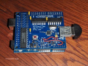 Bluetooth Part 1: Introduction
1. Background
These articles describe how to interface PS3 and Wiimote game controllers directly onto the Arduino using the USB Host Shield. These controllers have not previously been directly connected to an Arduino due to the USB and Bluetooth interfaces and protocols used, and their relative complexity. The game controllers are a good match to the capabilities of the Arduino, and to the imagination of Arduino users, they have not only buttons and joysticks, but also motion sensing, and other goodies which deserve to be in the hands and ideas of Arduino users. Also I hope these articles provide some guidance for people to develop other USB host and Bluetooth applications for small embedded processors.
Arduino already comes in versions which have USB and Bluetooth interfaces, but these are not suitable for our chosen game controllers. When used in USB mode, the PS3 controller is a USB device and needs to talk to a USB host. The normal Arduino USB interface is also a device, so not compatible. When in Bluetooth mode, both of these game controllers use the Bluetooth HID protocol and this is not compatible with the commonly used Bluetooth modules which support only the RFCOMM Serial Port Protocol. Arduino users have successfully used a PC as an intermediary between the game controllers and the Arduino, so the PC is host to both devices.
These articles were written by Richard who is new to the Arduino, blogs, github, libraries, etc, so please give me any help and feedback on how I might improve or correct these articles and software.
Continue reading PS3 and Wiimote Game Controllers on the Arduino Host Shield: Part 1
By Richard Ibbotson  PS3 controller connected to Arduino USB Host Shield Another HID example has been added to Github repository of USB Host Shield for Arduino (which you can purchase in my store) . Richard Ibbotson sent me this nice piece of code along with some pictures. He also posted a short description of his sketch in comments section:
I wrote a sketch for the interface of the PS3 controller over USB. I have two controllers, one Sony and one Madcatz wireless with a USB dongle. Both of these work fine to the USB host shield. I only made one minor change to the library to increase the NAK count. The sketch tests all the function, buttons, joysticks, accelerometer/gyro, leds and rumble. This is not yet under bluetooth just USB. I can set the host bluetooth adddress on the controller though which is needed for bluetooth pairing.
Did not make much attempt to reduce code or data size, so only have about 4K of program space and 240 bytes of data space left, but sketch is pretty long. The actual PS3 part is very small and could be made to a small library.
Next is to move to the bluetooth part, from what I have found on the direct USB, I am pretty confident this will fit even on the 168.
PS3 controller support opens some very interesting possibilities. Not only can it be used as a normal “joystick plus buttons” type of control, but you can also utilize it’s accelerometer/gyro. With wireless variant of the controller all kinds of very powerful radio control are possible. Who is going to be the first to make a mechanical dog, which follows you around and brings back the controller when you throw it away?
If you want to try the sketch, make sure you have the latest library code as well – there are some small but important changes made recently in NAK handling.
 MadCatz wireless controller to USB Host Shield |
 Wireless mini keyboard connected to USB Host Shield |
|
|


