|
|
By Oleg Mazurov  Magnetic probe amplifier connected to external trigger input I made (hopefully) last iteration of magnetic probe amplifier board. Schematic remains the same. Layout, however, is slightly different. First, I made it more narrow to better fit Tektronix 7000-series time base plugins external trigger input, as can be seen on the title picture. Second, the amplified probe output is made via SMx type connector – PCB-mounted SMA and SMB all have the same footprint. I used straight SMB since I have a surplus of Tektronix P6041 cables. The board layout permits soldering right-angle connector here as well. This arrangement is much handier than previous one.
Since publishing initial design I haven’t seen much interest in it, so instead of ordering a bunch of PCBs I made this board available on BatcPCB Marketplace. Schematic and board layout in Eagle 5.x format are also available. I built one board and haven’t found any errors on copper or silkscreen – if you find any, please let me know.
Oleg.
By Oleg Mazurov
|
In previous article I started talking about constructing magnetic stirrer from PC fan, a pair of rare earth magnets, and plastic can. In this article I will show the rest of the construction as well as program code to control the motor.
When building cases for my designs, I tend to avoid techniques requiring accurate (read “any”) measurements and calling for non-round holes. The design that I’m describing here is no exception. In order to complete it I needed just a few extra parts in addition to plastic joint compound can, PC fan and magnets, arrangement of which was described earlier. I used Arduino controller equipped with Motor Shield from Adafruit to supply PWM current to the fan, 3 nylon standoffs with adhesive bottoms to mount Arduno, rotary encoder to set stirrer speed, and panel-mounted 2.1mm DC power jack. The stirrer is powered from 12V wall wart capable of supplying 300mA or more.
I was thinking of implementing monitoring of motor current to track the moment when stirrer bar loses attraction to the magnets and stops rotating. When I was playing with the stirrer powered from bench suplly the change in current was quite visible. However, I found out later that when motor is supplied with PWM signal, current stays almost constant over the whole range of duty cycles and loads and current tracking won’t work. With regret, I abandoned this clever feedback idea. On the bright side, the code necessary to control the stirrer immediately became much simple, short and easy to understand.
|
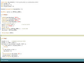
 Stirrer code |
Continue reading Vigorius stirring redefined. Part 2 – electronics
By Oleg Mazurov  Tornado in the flask Magnetic stirrer is a handy tool to help in any household activity, where agitation or mixing of relatively small (under 4L/1Gal) volumes of liquid or suspension are involved – from yeast starter preparation to dissolving fertilizer to chemical experiments. As almost any piece of laboratory equipment, factory-made magnetic stirrers are way overpriced. At the same time, such stirrer is rather easy to make from junk lying around the house. There are plenty of information on the Internet describing building mechanical part of a stirrer. Google for other people’s projects, some of which are much nicer than mine. I started this project mainly to play with motor control piece so mechanical setup was simplified as much as possible. As far a motor control goes, the main difference of mine will be ability to track stirrer bar behaviour. When a bar is spinning close to the maximum speed for given viscosity, it tends to lose strong attraction to the magnet of a motor and stop. Usual remedy is then to slow down the motor until it catches the bar and slowly increase the speed. Since moment of losing attraction is easy to register by monitoring current to the motor, the process of catching the stir bar can be automated. Also, I have a suspicion that a current change will be observed just before the disconnection and can be avoided altogether by corrective action. I will check this possibility during control circuit firmware design. Now, while waiting for Adafruit Motor/Stepper/Servo Shield for Arduino kit to join piles of junk lying around the house, I will describe mechanical implementation of the stirrer.
Continue reading Vigorius stirring redefined. Part 1 – mechanics.
|
|


